 EN
EN

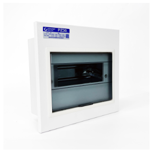
Foundations of MCB Box Wiring: NEC 2026 Compliance and Core Principles
NEC 2026-Compliant Conductor Sizing, Routing, and Spacing Requirements
Effective MCB box wiring begins with conductor selection that strictly follows NEC 2026 guidelines. The ampacity of each conductor must align with the overcurrent protection device rating to prevent insulation breakdown before the breaker trips. For a typical 20A branch circuit, 12 AWG copper is the minimum standard—but derating factors are non-negotiable. When multiple conductors share a raceway, heat buildup requires ampacity adjustment: NEC 2026 specifies a 70% adjustment factor for 7–9 current-carrying conductors. That reduces a 12 AWG wire’s effective capacity below 20A, often necessitating an upgrade to 10 AWG—a decision that directly affects terminal compatibility and enclosure space planning.
Routing within the panel must enforce strict separation between power and control wiring. A proven practice routes power conductors along the enclosure’s perimeter while routing control wiring through a central duct—reducing noise coupling and improving thermal management. Spacing is now a codified requirement: NEC 2026 clarifies that a ¼-inch air gap between parallel conductors is the baseline for heat dissipation in non-vented enclosures. This prevents thermal shadowing, where one conductor pre-heats its neighbor. Field data from the Electrical Safety Foundation (2023) links 15% of panel failures to cascading thermal events caused by inadequate spacing. Wire management accessories—such as bend-radius guides—ensure routing preserves insulation integrity at sharp corners.
Torque Verification Protocols and Terminal Integrity Standards
Torque verification is a quantifiable defense against high-resistance faults—the leading cause of thermal runaway in MCB box wiring. A loose terminal can generate localized temperatures exceeding 200°C, degrading insulation and damaging the breaker body well before the bimetal strip reacts. NEC 2026 Article 110.14(D) mandates calibrated torque tools applied per the manufacturer’s specified value; “firmly tight” is no longer acceptable. A 2022 industry survey found that 58% of thermal damage incidents in distribution panels stemmed from under-torqued connections—underscoring the critical gap between perception and mechanical reality.
The protocol follows a two-step process: initial seating followed by re-verification after a 15-minute settling period. This accounts for copper creep—cold flow that can reduce clamping force by up to 10% within the first hour. Calibrated, insulated torque screwdrivers eliminate human variability. While standard tolerance for 15A–60A circuit breaker terminals typically falls between 2.5–3.5 N·m, this value is manufacturer-specific and must be verified on-site. Post-installation, visual inspection of strand alignment is essential: a single stray strand outside the terminal lug can reduce contact surface area by 30%, creating a dangerous hot spot. This level of precision ensures long-term system reliability.
Safety-Critical Execution: Arc-Fault Prevention and Ground-Fault Validation
Physical Separation Strategies and Enclosure Design for Arc-Fault Mitigation
Arc-fault mitigation starts with physical separation strategies mandated by NEC 2026 Article 240.87. Enclosures with segregated compartments for line, load, and control conductors significantly reduce phase-to-phase arcing risk from insulation wear or vibration. Maintain a minimum 20 mm clearance between exposed live parts of different polarities and use non-combustible barriers compliant with UL 508A. Route high-current branch circuits perpendicular (90°) to signal-level cables—and sleeve crossings with fire-resistant material—to minimize electromagnetic interference and arc propagation paths. In multi-row C-bus installations, dedicate separate zones for power and control circuits and install arc shields around main incomers to contain flash events. Field studies cited by IEEE (2023) show enclosures with dedicated arc-quenching zones reduce arc-fault incidents by up to 40%. Enclosure selection must also consider IP-rated ingress protection to prevent conductive dust accumulation—a common arc trigger. These design choices form the foundational layer of arc safety, complementing the MCB’s internal arc-extinguishing mechanism.
Pre-Commissioning Ground-Fault Loop Impedance Testing (IEC 61439-2 & NEC 250.2)
Pre-commissioning ground-fault loop impedance testing is mandatory for all MCB box wiring assemblies to validate the fault-current path per IEC 61439-2 and NEC 250.2. This test measures total loop impedance (Zs) from supply source through live conductors and back via the protective earth—ensuring the MCB will trip rapidly under fault conditions. The pass criterion is Zs ≤ Uo / Ia, where Uo is nominal line-to-ground voltage and Ia is the current required to trip within the specified disconnection time (e.g., 0.4 s for socket outlets). Using a calibrated earth-fault loop impedance tester at the most remote point verifies that connections, cable lengths, and terminal torques meet design intent. Industry data from EC&M (2024) shows roughly 18% of newly installed commercial panels fail first-attempt testing—most commonly due to undersized earthing conductors. IEC 61439-2 further requires the assembly manufacturer to declare the maximum permissible Zs, which field measurements must not exceed. All results must be documented in the commissioning report, establishing a verifiable baseline for future periodic re-testing and ongoing NEC compliance.
MCB Selection and Integration for Optimal MCB Box Wiring Performance
The reliability of MCB box wiring begins with precise alignment between protection characteristics and connected load profiles. Selecting the wrong trip curve or rating risks nuisance tripping—or, critically, failure to trip during actual faults. The following sections detail the essential selection criteria and thermal management practices every installation must incorporate.
Type Curve (B/C/D) and Rating (1A–10A) Alignment with Load Profiles
Select the MCB’s trip curve so normal inrush currents remain safely below the magnetic trip threshold, while fault currents trigger instantaneous interruption. Curve B (3–5× rated current) suits purely resistive loads like lighting and heating—a 6 A B-curve MCB reliably serves a 1 kW lighting circuit. Curve C (5–10×) handles moderate inrush from small single-phase motors, control transformers, and contactor coils; a 4 A C-curve unit typically powers a 0.5 hp motor without nuisance trips. Curve D (10–20×) is reserved for very high-surge loads such as X-ray machines or large capacitor banks—and should never be used for general-purpose circuits in standard MCB box wiring. Within the 1 A–10 A range, matching the continuous current rating to expected load ensures the thermal element operates within its designed safety margin.
Thermal Derating and Layout Optimization in High-Density C-Bus Enclosures
In high-density C-bus enclosures, mutual heating elevates ambient temperature—reducing MCB current-carrying capacity. Standard ratings assume 30°C ambient; every 10°C rise may require 5–10% derating. For example, a continuously loaded 6 A breaker operating at 40°C effectively performs at ~5.4 A—increasing risk of premature thermal tripping. Counter this by maintaining at least 10 mm of air space between adjacent breakers and leveraging the busbar system to minimize wiring clutter and improve natural convection. Route high-current conductors away from MCB terminals and avoid placing heat-sensitive electronics directly above the enclosure. These simple layout adjustments preserve tripping accuracy and extend component service life.